One of the big challenges that I have been having with regards to cast iron restoration has been finding a cheap and reliable source of 12vDC power. Historically, many restorers have relied on manual car battery chargers, such as those made for Schumacher or Jegs. However, manual car battery chargers are becoming increasingly hard to find, are mislabeled (e.g. https://www.harborfreight.com/10250a-12v-manual-charger-with-engine-start-60581.html), or are expensive (>$100). Given these constraints, I wanted to find a means of 12vDC power that is cheap & ubiquitous, and I needed to look no further than a PC Power supply.
Background / Theory
The ATX Power Supply, The mainstay of desktop computers for the past 15 years or so, can easily provide > 10A of 12vDC power to power computer motherboards and other peripherals. As I planned out this project, I had to make a decision between two design philosophies. Do I completely convert the power supply so that I can only use it for electrolysis? Or do I somehow adapt the power supply non-destructively so that it is generally unchanged? I decided to do the latter as it allows me to easily swap out power supplies if (and when) they fail. Therefore, this build will demonstrate how to build a pluggable harness, which you can plug into any modern ATX power supply with the proper connectors to connect to an electrolysis tank.
This harness will use the EPS12V connector, which is intended to power high-wattage CPUs. (And if it is good enough to power a 140W CPU, Ohms law tells me that it should be able to provide ~ 11A of current (at 12vDC), which is more than adequate for electrolysis duties).
Required tools:
- Wire strippers
- Heat gun (or hair dryer).
Parts list
Many of these parts you probably have (after all if you are doing electrolysis of cast iron, you are pretty handy), but I am providing a complete list for reference purposes.
| Item | Link | Quantity | Price | Subtotal |
|---|---|---|---|---|
| Power Supply | LINK | 1 | 62.26 | 62.26 |
| EPS 12V power extension cable | LINK | 1 | 6.99 | 6.99 |
| 14 GA Stranded cable (Black) | LINK | 1 | 14.43 | 14.43 |
| 14 GA Stranded cable (Red) | LINK | 1 | 14.43 | 14.43 |
| 14-16 AWG Butt Connectors | LINK | 1 | 9.99 | 9.99 |
| Battery clamps | LINK | 1 | 4.31 | 4.31 |
| ATX Jumper bridge tool (Optional) | LINK | 1 | 4.99 | 4.99 |
Build Log
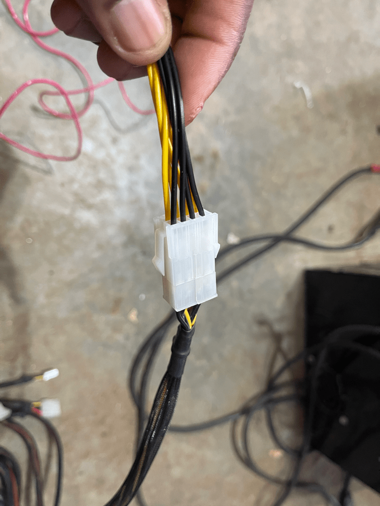
Firstly, we need to remove the male end of the EPS 12V power extension cable and strip about a half inch of each of the black and yellow cables.
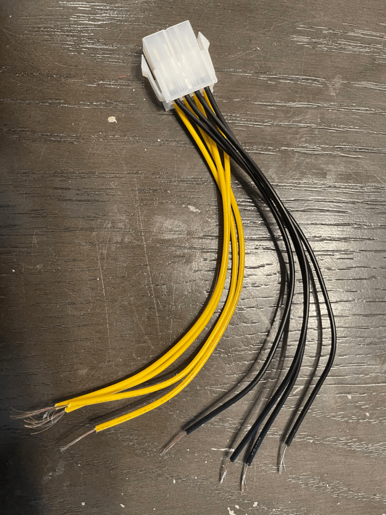
Next, twist together all 4 of the yellow cables, and optionally slide over a piece of shrink wrap tubing. Slide into one of the butt connectors. Repeat this for the black cables. When completed, it should look like the following:
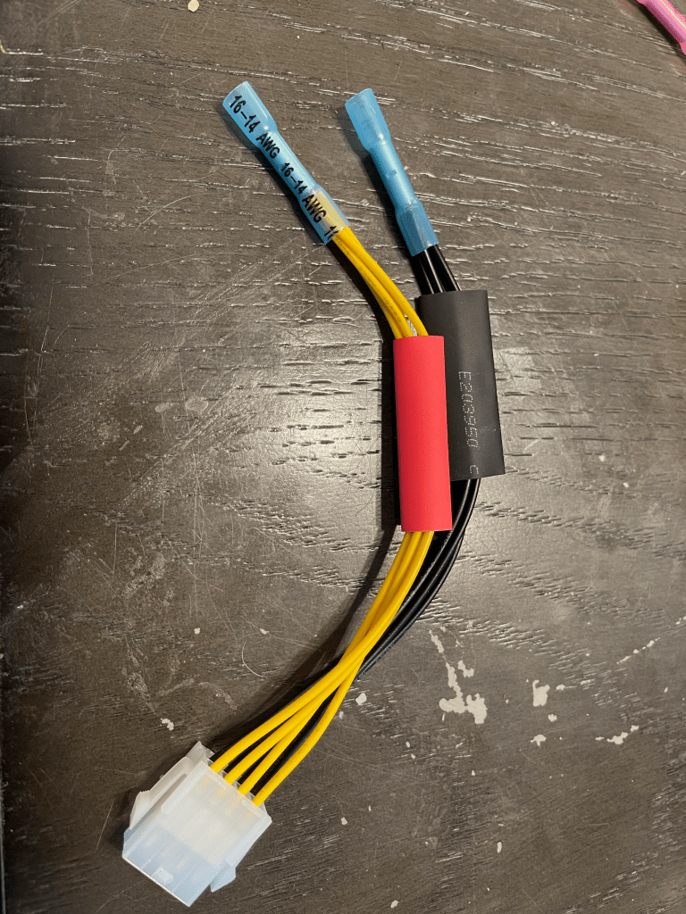
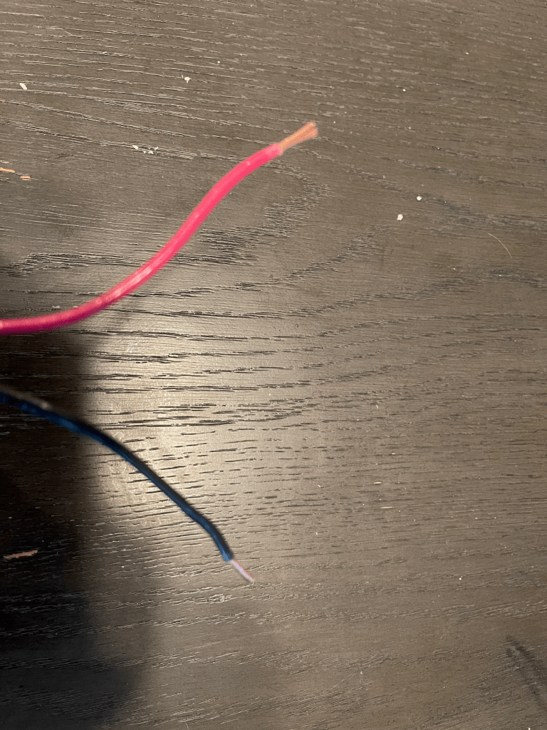
Next, cut a 6-8 ft strand of both red and black 14 gauge cable, and strip about 1/2 inch on each side. One side will go into the butt connectors, the other will attach to our battery clamps.
Insert the black 14 gauge cable into the butt connector with the black cables, and insert the red 14 gauge cable into the butt connector with the yellow cables.
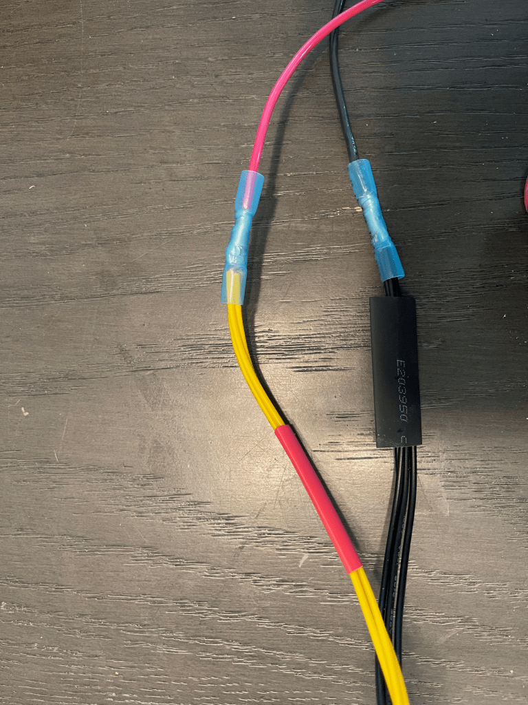
Next, using your crimpers (or a pair of pliers in a pinch), crimp both sides of the butt connectors. Slide the shrink tubing over the butt connectors and apply heat from the heat gun to shrink it.
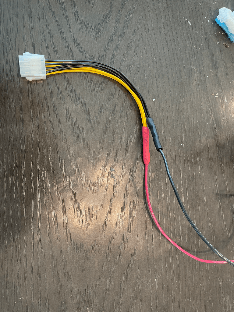
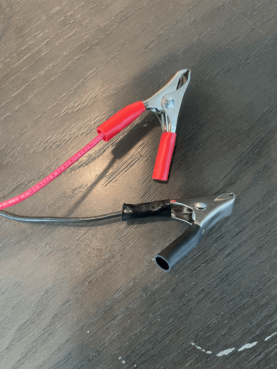
On the opposite end of harness (with the still exposed cables), attach the battery clamps

That’s it. Now we have a harness, which we can plug into the EPS12V connector of a power supply, with clamps so that I can attach it to my anodes and cathodes. Now, our next problem: How to get a PC Power supply to turn on without a PC?
Enabling a PC Power Supply to turn on
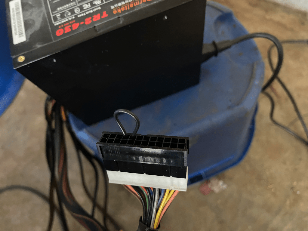
Looking at the ATX specification (courtesy of the Wikipedia article), we can: “If using an ATX PSU for purposes other than powering an ATX motherboard, power can be fully turned on (it is always partly on to operate “wake-up” devices) by shorting the “power-on” pin on the ATX connector (pin 16, green wire) to a black wire (ground), which is what the power button on an ATX system does.”

Using a metal paper clip, connect pins 16 & 17 (or any of the ground pins (labeled COM) to hardwire the power supply so that you can use the switch on the rear of the power supply to turn it on and off. Alternatively, if you’ve purchased the jumper bridge, just connect it to the entire 24-pin connector.
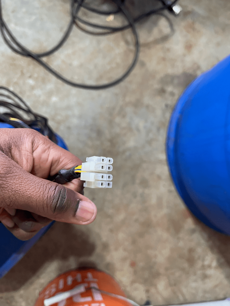
Lastly, attach the harness to the EPS12V connector (which is the 8 pin connector with 4 Yellow (12v) and 4 Black (Ground) cables). In some power supplies (like this one), it is setup as two 4 pin connectors.
Once connected, you can connect your clamps to your anodes and cathodes, and get to work.
Conclusion
For a relatively low cost, I can now grab a power supply and put it to work for electrolysis. And if the power supply dies, I can easily source another on Newegg, Amazon, or Ebay. In a future article, we will extend this design by adding an ammeter so that we can track current usage.

1 comments on “Adapting a PC Power Supply for Electrolysis: Part 1”