In Part 1 of this series, we covered how we can easily adapt a PC power supply to power an electrolysis tank. This was done using an EPS12V connector to build a ‘dongle’, which can be plugged into any power supply made in about the past 10 years or so.
In this part, we’ll build another dongle, this time adding an ammeter, so that we can measure current draw.
Required Tools
- Flat screwdriver
- Adjustable Wrench
- Wire Strippers/Crimpers
Parts list
As in the last post, you probably have most of these lying around, but again, I am stating the whole list for completeness.
| Item | Link | Quantity | Price | Subtotal |
|---|---|---|---|---|
| Power Supply | LINK | 1 | 62.26 | 62.26 |
| EPS 12V power extension cable | LINK | 1 | 6.99 | 6.99 |
| 14 GA Stranded cable (Black) | LINK | 1 | 14.43 | 14.43 |
| 14 GA Stranded cable (Red) | LINK | 1 | 14.43 | 14.43 |
| Battery clamps | LINK | 1 | 4.31 | 4.31 |
| ATX Jumper bridge tool (Optional) | LINK | 1 | 4.99 | 4.99 |
| Ammeter | LINK | 1 | 15.99 | 15.99 |
| Connectors | LINK | 1 | 14.79 | 14.79 |
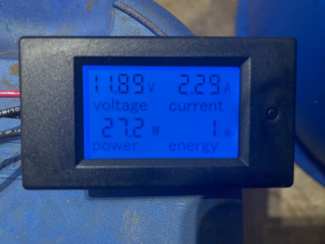
Ammeter
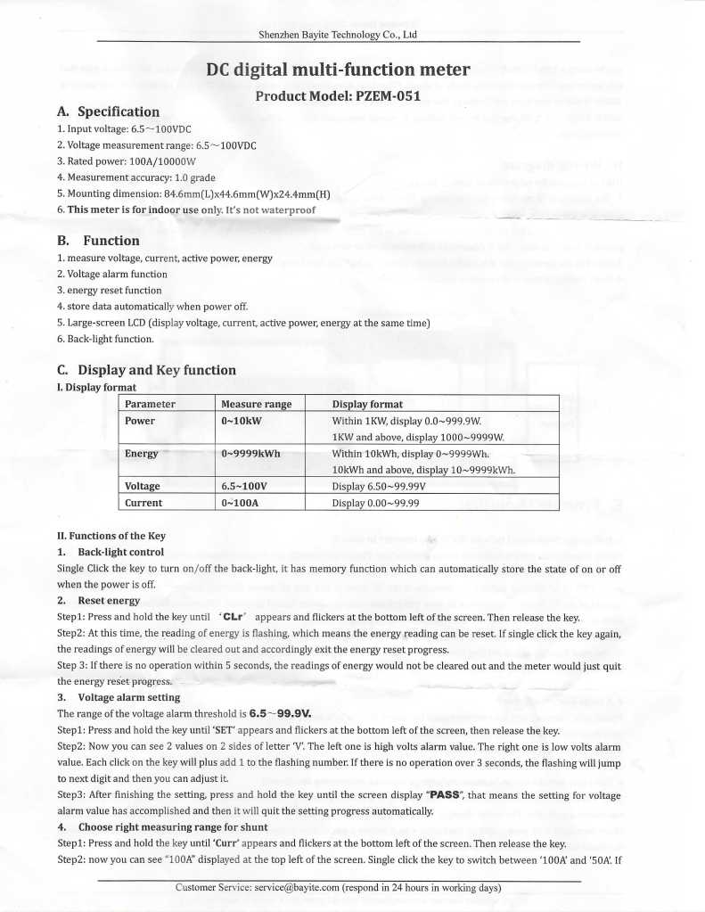
For this project, I selected this ammeter, made by Bayite

I selected this ammeter because it was cheap and had a shunt. The instructions online were kind of unclear, but included in the packaging when it arrived were a better set of directions, which I am posting below:

Build Log
Firstly, we need to remove the male end of the EPS12V power extension cable and strip about a half inch of each of the black and yellow cables.
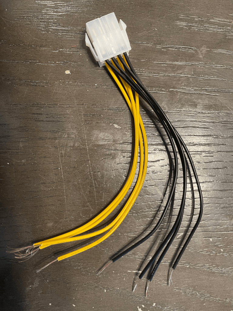
Next, take the 4 black connectors and connect them to a ring connector.
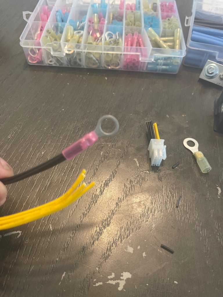
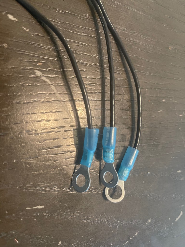
Next, pull out 3 lengths of black cable, roughly 6 or so inches long, and strip about a quarter inch on each side.

Connect ring connectors on one end of EACH cable, leaving the other end bare. These ‘pigtails’ will have ring connectors that will be connected to the shunt, and the other end left bare to connect to the display.
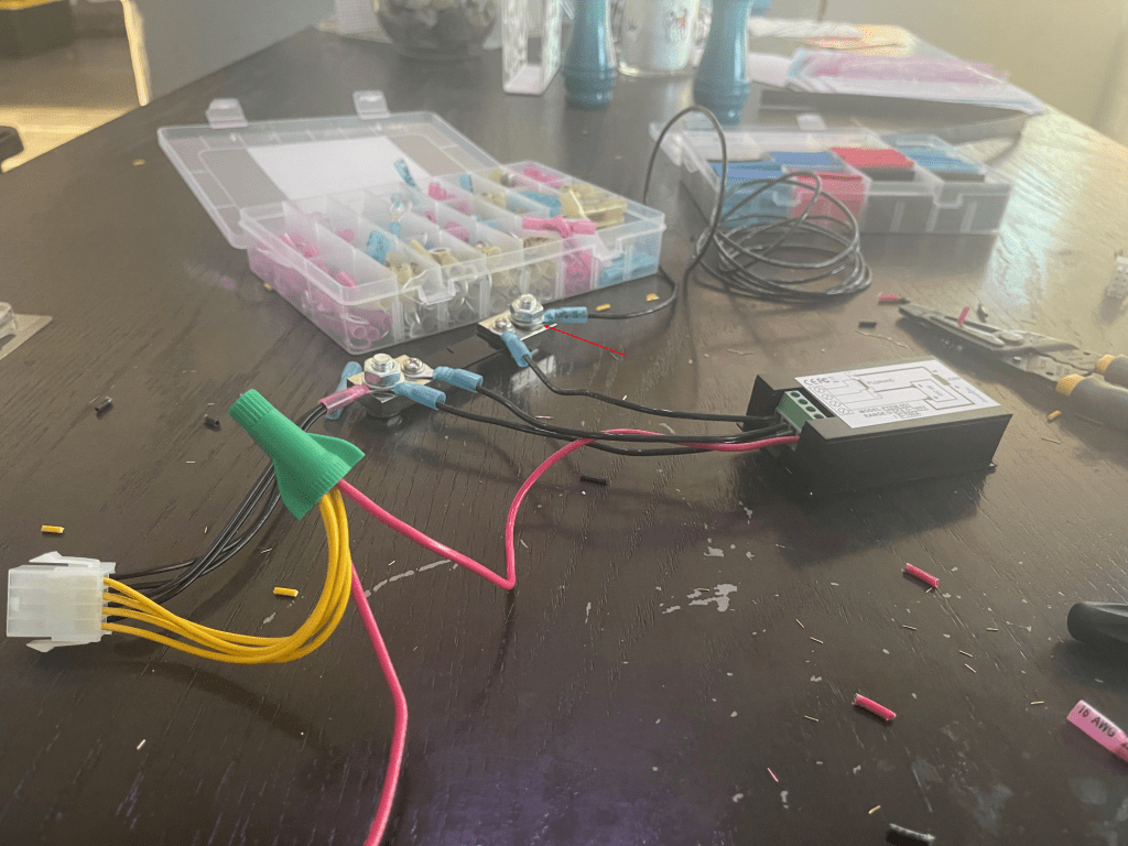
Next, attach the ring connector which is connected to the EPS12V cable and one of these pigtails to the bolt on the left side of the shunt.
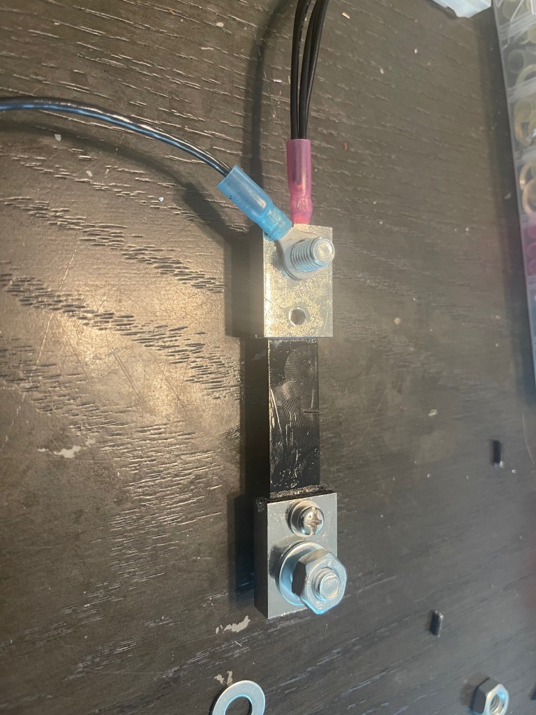
Apply the bare end of the pigtail into the display (at the 3rd screw – counting from top to bottom)
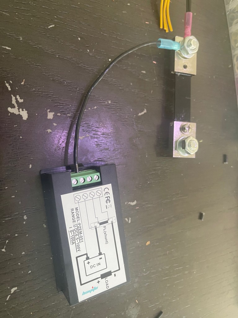
Next, take another of our pigtails, and connect that to the 2nd screw of the shunt. And connect the bare end into the 2nd screw of the display. (again, counting top to bottom)
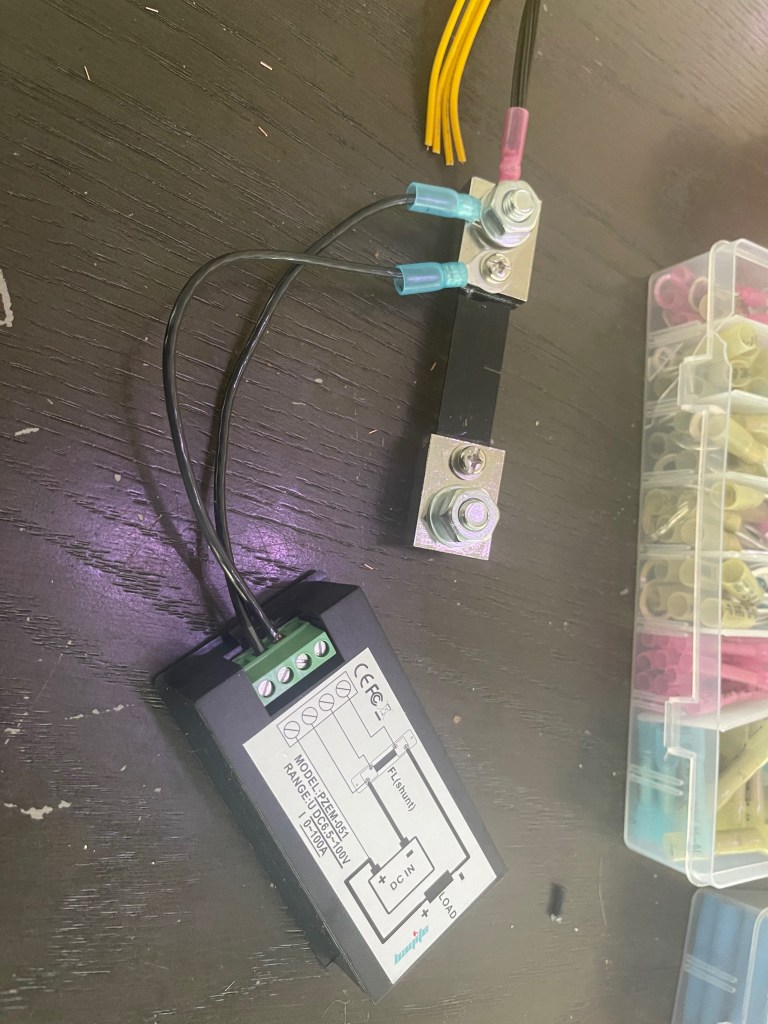
Take the 3rd pigtail, connect it to the 3rd screw of the shunt, and the bare end into the 1st screw of the display.
Now, to connect the positive side to the display, we’ll need to:
- Use a short length of red cable (bare on each end) to connect to the display
- Use a longer (~ 6 ft) red cable (bare on each end) to connect to the electrolysis tank.
- Connect the above two cables and the 4 cables from the EPS12V connector together.
I used a wire nut for this.

Connect a 6 ft length of black cable to the 4th screw of the shunt with a ring connector.
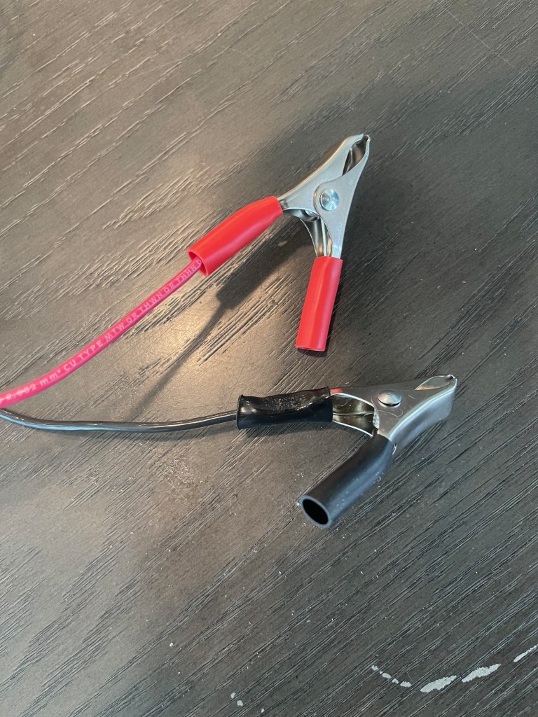
Lastly, connect the remaining bare ends of both the red and black cables with clamps and this contraption is ready to go.
And finally, I can plug the harness into the ATX Power Supply, connect the clamps to my electrolysis tank, and fire it up.
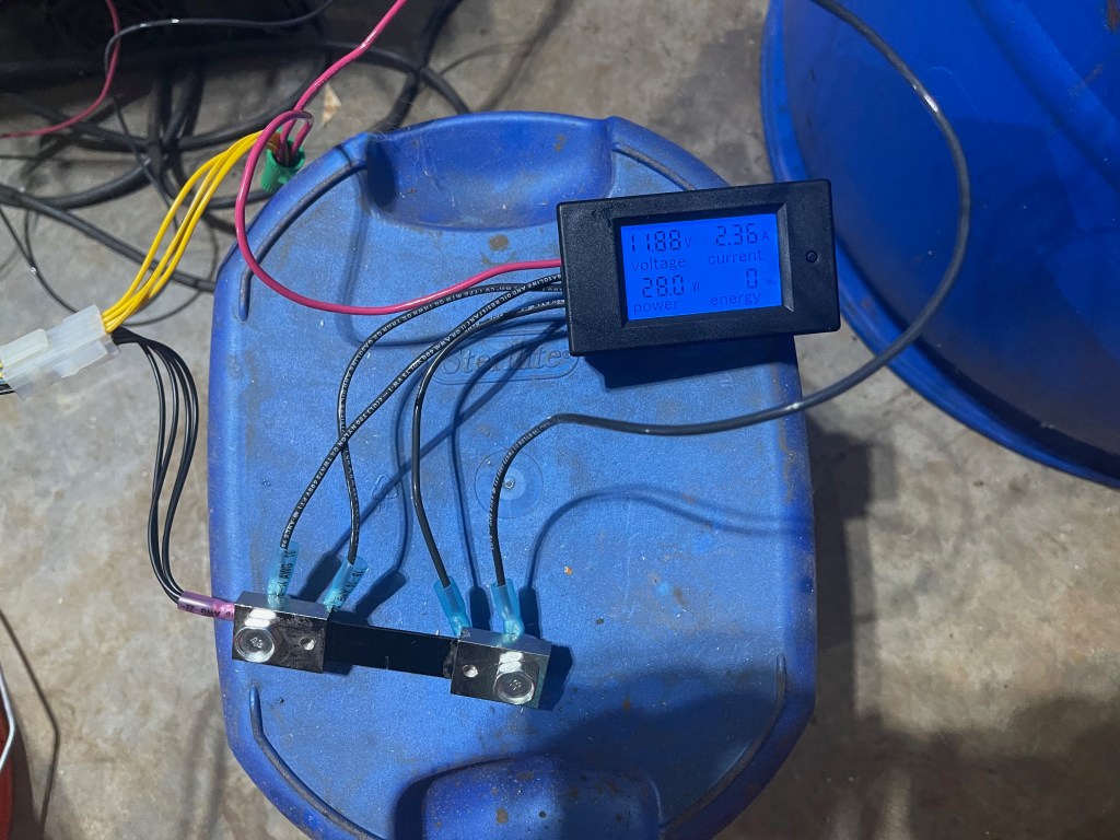
Conclusion
Now with a proper ammeter, I can now track the current draw of my electrolysis tank. I hope these articles help you to understand how to adapt a PC power supply to power an electrolysis tank. Additionally, with a near infinite supply of PC power supplies available in the market, you shouldn’t have to struggle to find a means to power your e-tank again.
